Thursday, May 15, 2014
Wednesday, May 14, 2014
071_analogue testing_kinetic object + proximity sensor
Testing the final analogue device with the proximity sensor above. Initially the movement in the flexinol was extremely small and not enough to move the "wing" (about 2mm of movement).
This was solved by "programming" the flexinol into a coil shape, by winding the flexinol around a metal rod using clamps, and applying a high heat with the butane torch for 2 seconds to set it. It was important not to apply too much heat for too long as you risk damaging the wire.
The wire was then stretched out and secured in place, so that when a current was applied to the wire, it contracted back into a coil shape which pulled the wing up higher.
Sunday, May 11, 2014
Thursday, May 8, 2014
063_construction_wiring
Wiring for the analogue involved a 12v battery pack, ultrasonic proximity sensor, relay, 5v battery pack and flexinol wire. See previous posts for the testing of the sensor and relay.
Ultrasonic sensor with 0.0012 flexinol test
 |
| Circuit |
 |
| Layout on the neck piece |
062_construction_neck piece
The purpose of the neck piece is to provide a meaningful way to conceal the sensor and electronics required to produce the output.
The location of the sensor on the neck was chosen as it is generally sensitive location on a persons body with regards to touch. A tube style neck piece was selected as it restricts movement- potentially something that occurs to farmed.domesticated animals. Having this lessened ability to move reflects the vulnerability a person may feel with regards to proximity/distance away from an object or another person.
Inspiration of form
 |
| Isabelle McGuire and Mady Berry |
 |
| Michael Cepress |
 |
| Michael Cepress |
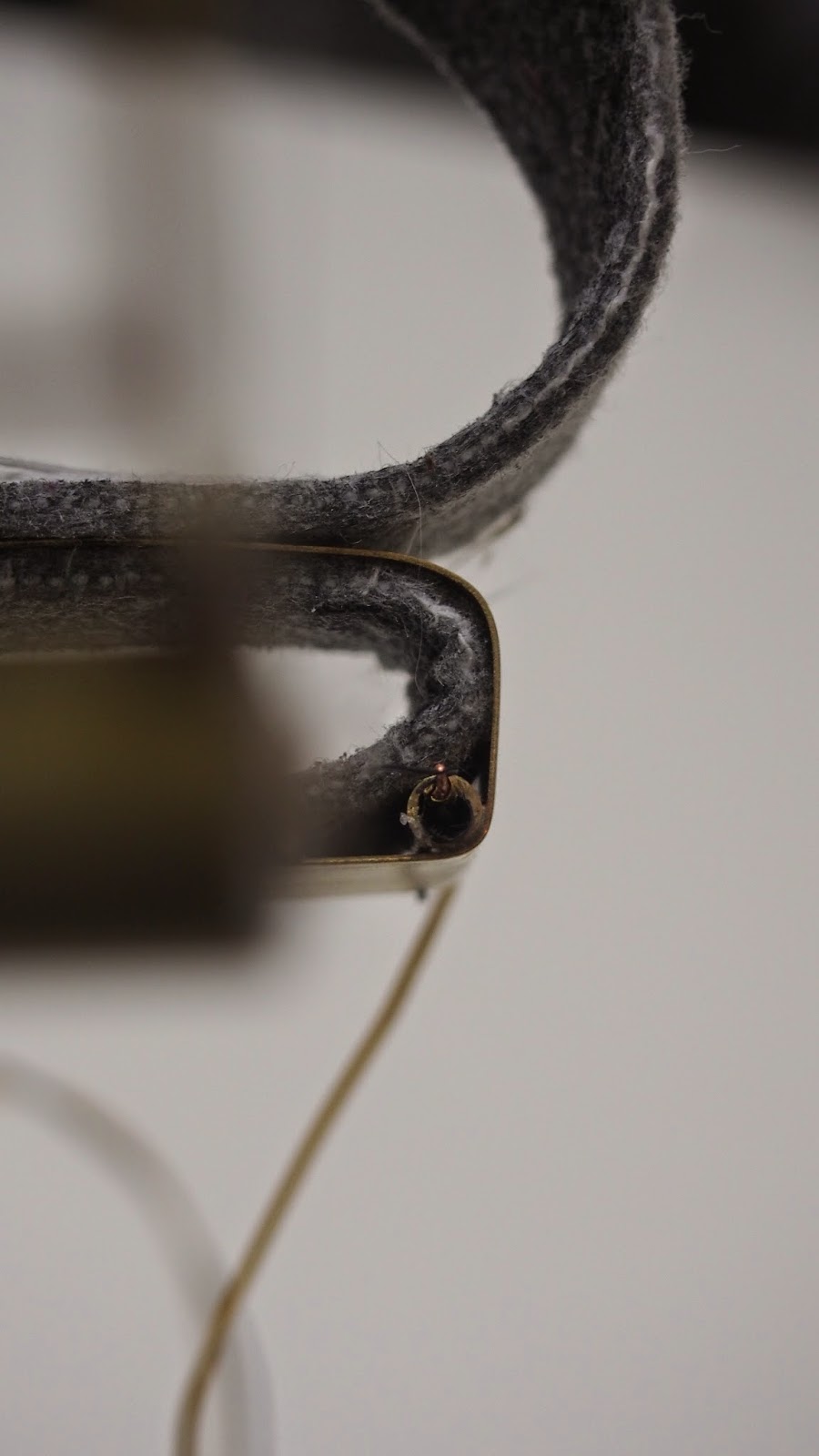
The construction of the neck piece involved sewing velcro to create a pocket to contain the electonics. Two holes were cut in the fabric to locate the sensors through. Various methods of fastening were tested using brass/elastic, however velcro was selected as the most robust and is hidden when the tube is placed on the person.
061_construction_brass structure
Instruments required
Butane torch + butane
Silver paste solder (hard)
Silver wire solder
Flux
Soldering brick
Tweezers/pliers
Jewellers mitre box and saw
 |
| Butane torch |
 |
| soldering brick and silver paste solder |
 |
| first attempt at soldering the box for the finger= fail |
 |
| soldering the wing piece |
 |
| Structural components |
 |
| The wing |
 |
| Ring |
 |
| Runners and structure |
 |
| Soldering components together |
 |
| Nearly finished structure |
Polishing
Subscribe to:
Comments (Atom)


