The purpose of the neck piece is to provide a meaningful way to conceal the sensor and electronics required to produce the output.
The location of the sensor on the neck was chosen as it is generally sensitive location on a persons body with regards to touch. A tube style neck piece was selected as it restricts movement- potentially something that occurs to farmed.domesticated animals. Having this lessened ability to move reflects the vulnerability a person may feel with regards to proximity/distance away from an object or another person.
Inspiration of form
 |
| Isabelle McGuire and Mady Berry |
 |
| Michael Cepress |
 |
| Michael Cepress |
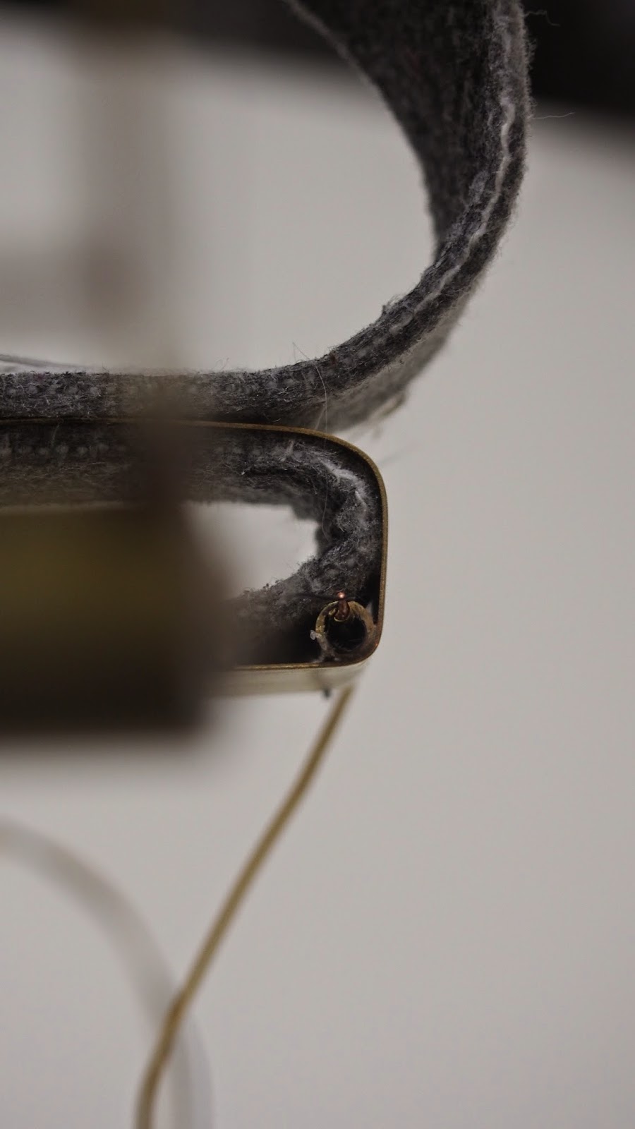
Construction
The construction of the neck piece involved sewing velcro to create a pocket to contain the electonics. Two holes were cut in the fabric to locate the sensors through. Various methods of fastening were tested using brass/elastic, however velcro was selected as the most robust and is hidden when the tube is placed on the person.